
Mid-Range Tankers
B Marsden
As it had done since the early 1970s, the North Altona Fire Equipment Development Centre continued to operate, through the 1990s, as an innovative R&D centre. In the mid-1990s the Centre developed slip-on fire-fighting modules for use with the Mitsubishi Canter 4x4, and the Isuzu NPS 300, 4x4 tray vehicles. The fire-fighting modules were assembled with three different tank capacities: 1000 litre, 1200 litre and 1500 litre. The configuration of each vehicle, whether a single or twin cab, or whether a crane was installed, would impact on the water-carrying capacity. The 1000 litre capacity slip-on module was developed for the smaller Mitsubishi Canter when fitted with a crane. (Fig 1) The 1200 litre module was developed for the Isuzu NPS 300 with a crane, and the 1500 litre for the twin cab Isuzu NPS 300 without a crane.
Why Are They Called Mid-Range?
The development of the mid-range modules provided additional capability for the Mitsubishi Canter and Isuzu NPS 300 4x4 vehicles when supporting the larger tanker fleet at emergency situations. The water capacity was less than the larger 4000 litre fire-tankers, but greater than the smaller traditional 400 litre slip-on fire-fighting units fitted to Land Cruiser and Nissan one tonne capacity 4x4s, that were the standard unit at the time.
Construction
The fire-fighting modules consisted of a UV stabilised polyethylene or fibreglass tank mounted to a purpose built heavy-duty tubular metal frame, along with an overhead full length galvanised mesh equipment cage which provided ample storage for suction hoses and hand tools. A 38m Davey Firefighter pump, Dosatron foam injection unit, two external live hose reels, and a mounting bracket securing two 20 litre fuel jerry cans were also attached to the frame.
Standard Slip-on
The standard mid-range modules could deliver water at the nozzle, or aspirated foam through a foam branch, when the foam injection unit was activated.
Hi-Pressure Slip-on
In some instances a Hi-pressure pump replaced the Davey Firefighter pump, and the two live reels were equipped with 50m of 20mm Super S PVC hose, which could deliver an extended jet stream of water, or aspirated foam. to burning embers in tree tops. (Fig.2)
What is Aspirated Foam?
Aspirated foam assists the firefighter by reducing the surface tension of water being delivered (similar to dish-washing liquid) and allowing the foam to penetrate forest fuels and not form droplets and run off in beads.
See also this article about foam
Why Add Air to the Water/Foam Stream?
The same slip-on modules were also fitted with a 15 cu.ft/min displacement twin air compressor, close-coupled to a 5.5 HP Honda petrol engine, as an added feature which could deliver compressed air into the water foam delivery stream. (Fig.3)
What is Compressed Air Foam?
Adding compressed air to the water foam stream provides greater discharge distance at the nozzle and delivers more stable foam, similar to shaving cream, consisting of small tight uniform slow-draining bubbles. Compressed air foam will adhere to both vertical and ground fuels, and will take longer to break down due to its uniform bubble structure.
What Foaming Agent Was Used?
Only approved Class A foams that had undergone a US Wildland Chemical Qualification and Testing Program were used.
Tank Positioning
The positioning of the tank on the tray was critical to ensure that the correct weight distribution was achieved. If the tank was too far forward the front axle may be overloaded and, similarly, if the tank was too far back there may not be enough weight on the front axle. (Figs. 4a & 4b)
Mounting Attachment
The slip-on modules were secured to the vehicle tray by six heavy duty toggle mounts, providing a standard fixture when in use. (Fig. 5)
Vehicle Versatility
During winter months the slip-on modules were removed, allowing the mid-range 4x4 vehicles to be used on alternative work programs. i.e. they became a normal works vehicle. Twin-cab vehicles provided additional seating for the transport of a works crew and the inclusion of a crane (if fitted) provided the means of loading heavy equipment such as culverts for repair works on forest roads. (Fig. 6)
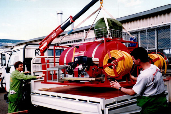
Fig. 1 Mitsubishi Canter 4x4 Crane installing a 1000 litre slip-on module
1993
Photo: B Marsden
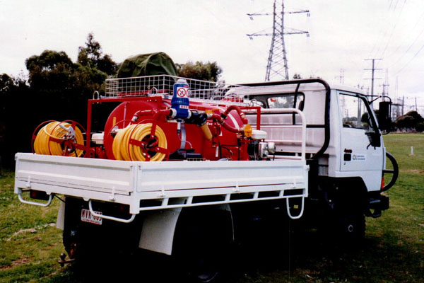
Fig. 2 1000 litre slip-on module on a Mitsubishi Canter 4x4 with crane fitted
1993
Photo: B Marsden
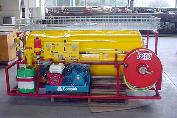
Fig. 3 1200 litre slip-on module showing D1 16 Dosatron foam injector, control panel and air compressor
2004
Photo: B Marsden
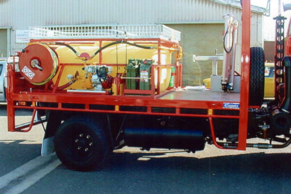
Fig. 4a 1200 litre slip-on module mounting position on an Isuzu NPS 300 single cab tray, also fitted with a Hi-AB crane installed forward of the tank. Driver side view.
2004
Photo: B Marsden
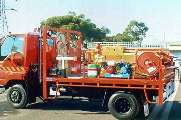
Fig. 4b 1200 litre slip on module mounted on an Isuzu NPS 300 4x4 single cab tray; crane installed front left hand corner of tray. Curbside view
2004
Photo: B Marsden
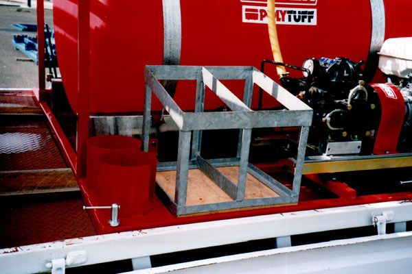
Fig. 5 Standard slip-on toggle mount installed at one corner of a mid-range slip-on module
1999
Photo: B Marsden
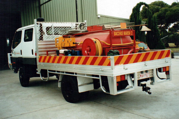
Fig. 6 1500 litre slip-on module mounted to a Bacchus Marsh Isuzu NPS 300 4x4 twin cab tray vehicle with no crane installed
1999
Photo: B Marsden
Storage
Slip-on modules were stored on pallets when they were removed from the vehicles. This allowed them to be easily accessed and installed by a fork lift or gantry when required, or by an on-board crane if fitted.